
Apologies in advance – this is going to be a long post (and it has a lot of pictures).
My engine install actually started with more preparation: covering the chassis tubes with pipe lagging and cutting strong cardboard for the footwell heat-shielding.

Pipe lagging 
Strong cardboard to protect the foot-well 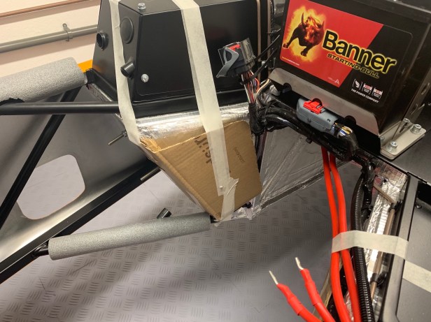
Cardboard in place
I also wrapped the widest part of the gearbox with several layers of strong polythene (which was the bag the gearbox came in). The idea here is, sooner or later the gearbox is going to touch the side wall of the transmission tunnel which isn’t in itself a problem, but the gearbox’s sharp edges will damage the heat-shield or powder coat, so the polythene blunts of these edges. Make sure the gearbox output shaft plug is still in place, because the Caterham 5-speed Mazda gearbox is supplied full of oil, which is best kept in the gearbox.

The cam cover is actually very difficult to source as a spare part, and replacing it would lose your original manufacturing label, so several layers of masking tape was applied and a I covered it with a towel to protect it even more.
It’s not possible to install an engine into a Caterham in my garage without either the engine hoist or the chassis beginning the process being outside – my garage just isn’t long enough. To make matters worse, my garage is also on a slope, so I chose to start with the chassis outside. Pushing the chassis uphill is easier at this stage, because it’s lighter than the engine and gearbox. Thankfully the weather was perfect for the install.
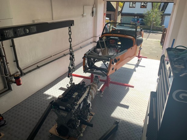
Making space for the install 
Chassis starts outside the garage 
Engine hoist ready
The ability to move the chassis during the install isn’t necessary, but it does make life easier. If you don’t have wheeled axle-stands, then all the movement has to come from the hoist. The down side to this is that the hoist is harder to move (because it’s holding more weight) and the engine will tend to swing when you stop moving it, which is unwanted.
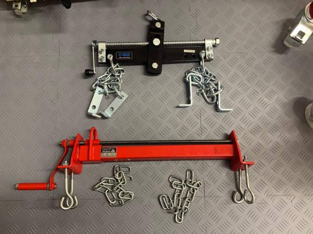
I use an engine load leveller when installing engines into a Caterham, to be able to adjust the angle of the engine during the install. There seem to be two main types on the market here in the UK: I have been using my Clarke strong-arm leveller (https://www.clarkeinternational.com/shop/product/details/cll500-load-leveller) for a few years now, but I decided to try the other style for this build, and I purchased an SGS leveller (https://www.sgs-engineering.com/sll680-load-leveller). Functionally, I would say there is very little difference between them, but I preferred the SGS because it didn’t flake red paint all over my engine.
If you are using the hoist and axle stand combination for the first time, check that your hoist has enough reach to get your engine into the chassis and clears your axle stands before you attach your engine. Given this isn’t my first Duratec install using this hoist and wheeled axle stands, I skipped this part, but I did have this in mind even when I setup the axle stands before delivery. If you look back on that post you will be able to see the front stands are assembled differently to the rear to make them narrower. I suppose it would be wise to check that you have the height above the car for the hoist as well.

Narrow as possible 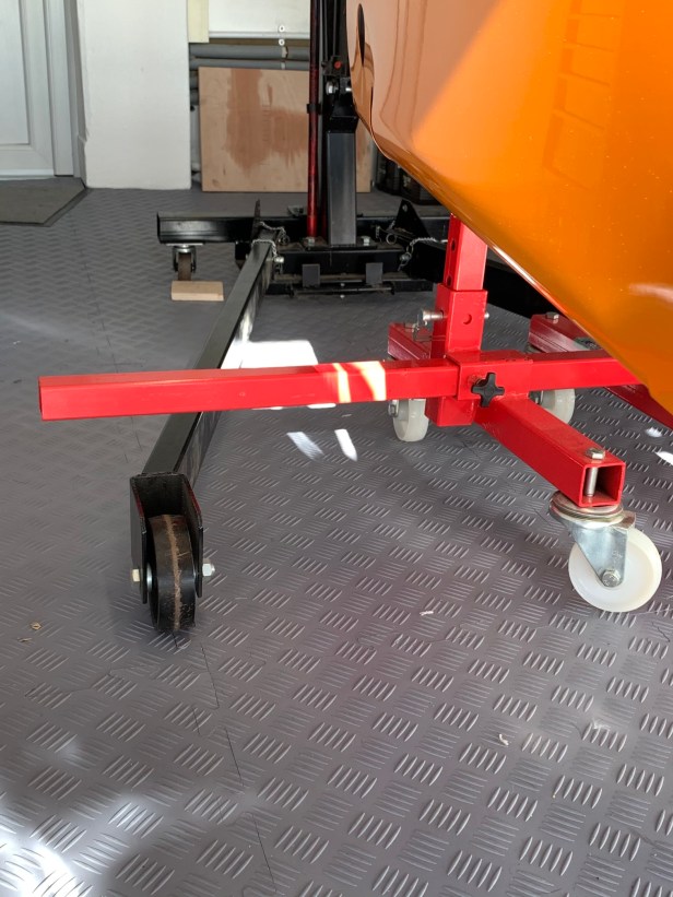
Hoist clears the stands 
Check you have the height
With the hoist setup and the load leveller attached the engine was lifted, and levelled as best I could, but not being designed for inline installation brings some unique challenges. The first is a benefit: the engine – even with the leveller at maximum (the end stop) – has a slight angle with the gearbox pointing to the ground. This is ok and simple to rectify with a jack near the end of the install, but more on that later. The second challenge, and the one that causes the biggest problem during the install, is the twist. You can see this from the picture of my first attempt to install my 360 engine back in 2016. The twist presents the gearbox at a different angle and therefore wider – and in extreme situations it simply won’t fit into the transmission tunnel.

My solution to the twist comes from a ratchet strap attached to the left hand engine mount. You want a good quality ratchet strap, I think mine is rated for 250Kg. Caterham recommend an engine hoist capable of lifting 150Kg, so the strap should be man enough to take the load, and it does so as angle is applied. Most importantly, it keeps the twist under control although it cannot remove it completely.
Remember to check the left hand engine mount is secure before you start (and double-check all the lifting eyes for that matter).

Strap to stop the twist 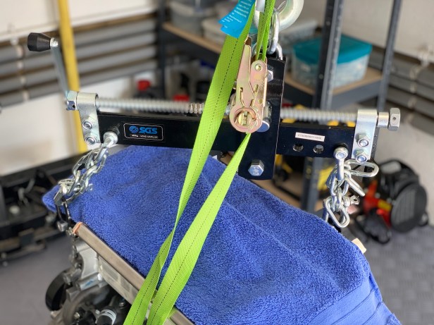
Leveller and chain setup 
Adjust to get as level and twist free as possible 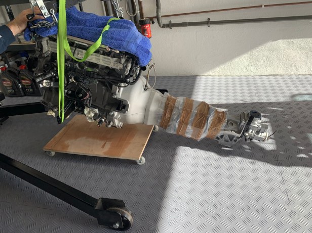
We have lift off
At this point do not continue without assistance. An extra pair of eyes and a hand to steady the engine from rocking as it’s moved can be critical. My wife assists me and it’s fair to say it’s not her first time doing this, but she is still very much the novice mechanic. I had to remind her sometimes not to put her hands under the engine or in places where they could get trapped if something went wrong. If the hoist or the chains failed I would only want to have to deal with a smashed-up chassis / engine.
So, time to lift the engine and bring the engine to the chassis. You start as level as possible, and high enough to clear the chassis. Make sure that the chassis and engine are lined up as much as possible, look from a few different angles. The more accurate you are here, the easier the install will be.

Get the gearbox over the chassis 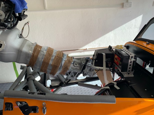
Start to increase the angle 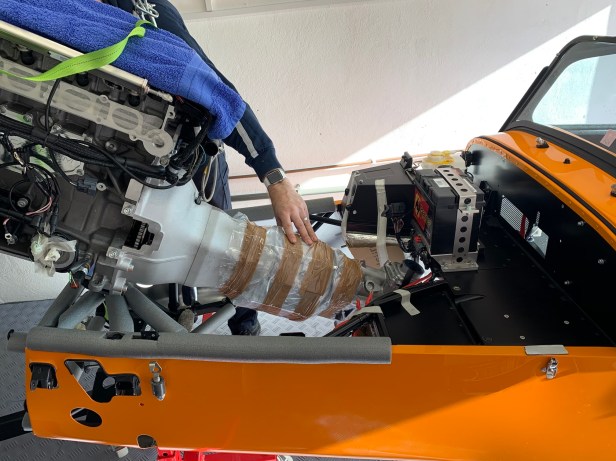
Lower the gearbox into the tunnel 
Keep the gearbox as high as possible 
Nice view of the sump 
Careful of the dry sump connections
Now lower the gearbox output shaft by increasing the angle using the leveller. And then start lowering the engine.
The process basically revolves around three actions: lowering, changing the angle (level) and moving the engine backwards into the chassis, all of which you want to do patiently, n a controlled manner. You will continue to perform one of these actions until you run out of space, and then you change to another action. Don’t be surprised if you can only move as little as 5mm at any one stage.
This part of the process can take a fair bit of time. I prefer to take my time and minimise any damage potential, therefore after each movement I check what’s going on in all the areas where the engine or gearbox are getting close to the chassis.
Initially you will be increasing the angle (steeper), but later in the install you will be reducing the angle (flatter or more level).
Don’t forget with a crane style hoist the engine moves back as its lowered.
Keep the gearbox high 
The front of the engine clearing the chassis 
As this stage lower and level the engine 
Time to lower 
Careful of the crank sensor wire
With the Mazda 5-speed gearbox you must not let the main body of the gearbox get lower than the chassis transmission tunnel. There isn’t the space (even without any twist) to raise the gearbox back into the chassis.
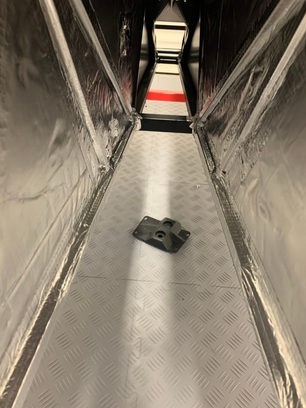
Keep an eye on the gearbox in the tunnel 
The gearbox is very close to the tunnel 
Gearbox in position 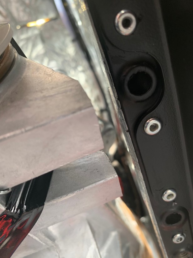
Mounting holes that need to be cleared
When the engine is close to the mounting points, it is time to resolve that first problem and bring the engine and gearbox unit up to level. This is done when the output-shaft of the gearbox reaches the transmission tunnel cross-bar (about half way down the chassis). You will need to use a jack to lift the gearbox output over the cross bar. The jack also sorts the twist (which is a bonus). You can see from my photos that I used a large lifting block and a small block, and even then the jack was at full stretch. This all depends how high you have lifted the chassis, and how much lift your jack has, so be prepared.
I would avoid putting tall wooden blocks on the lifting surface of the jack, you don’t want them slipping off as the engine moves. However, I have used wooden blocks under the jack before successfully.
The cross bar 
Time to support the engine with a jack 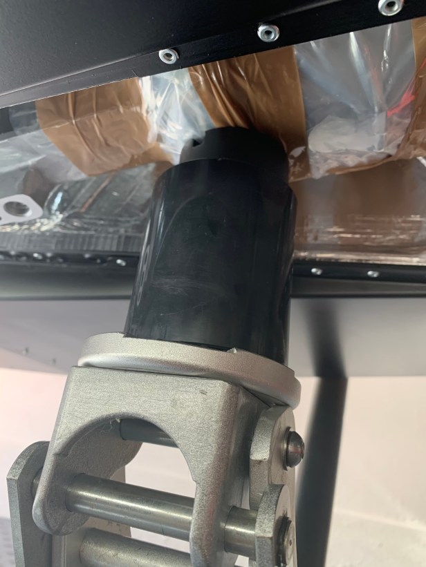
Lifting blocks in place
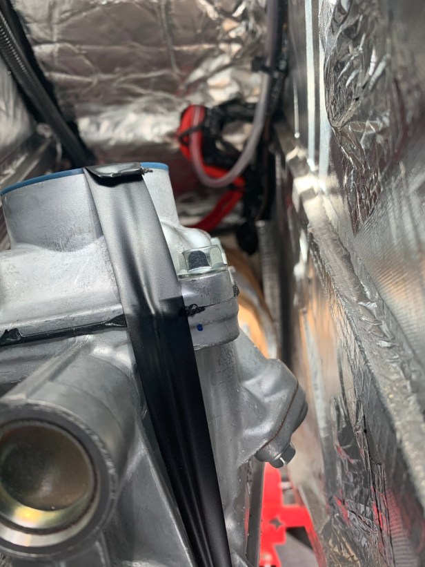
Remember, it gets very tight in places. I have taken some photos of the engine as it squeezes past the pipe lagging. Without the protective lagging the chassis would be damaged. From the photos you can see how the cardboard saved the heat-shield from damage.

Bell-housing and foot-well are very close 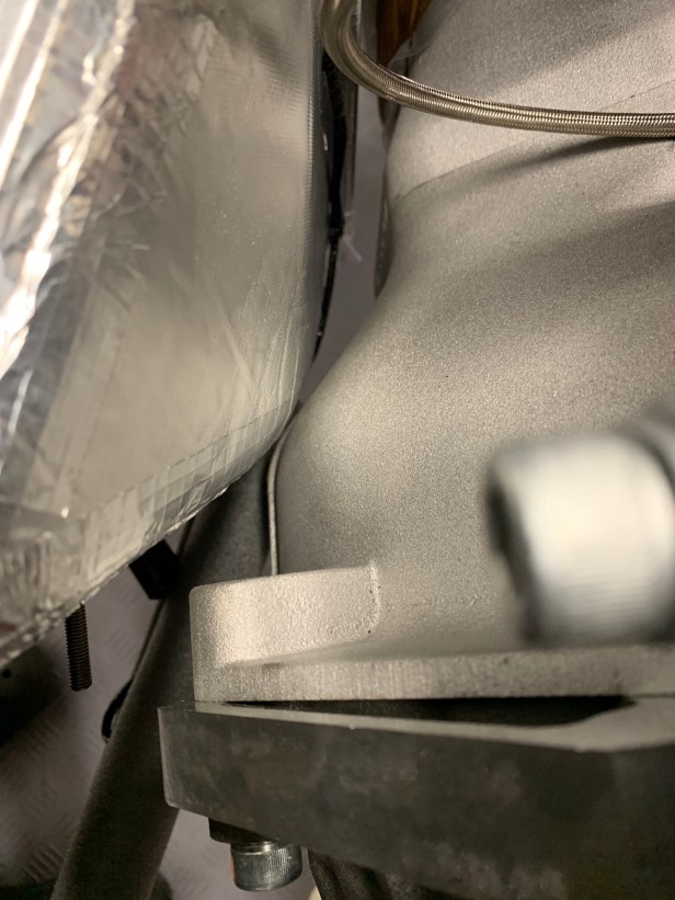
With cardboard protection removed 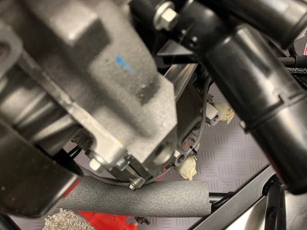
Lower chassis rail is very close to the engine 
Time to reattach the right hand side engine mount
However, I didn’t manage to achieve 100% “no damage”. It is my first attempt with the Mazda 5-speed gearbox, and I assumed the widest part of the gearbox would be the place that was most at risk of touching the heat-shield. This assumption proved to be wrong once the gearbox was deep in the transmission tunnel. It damaged some of the aluminium tape used to secure the heat-shield. This required a simple repair with a patch of new tape, which had to be applied before the gearbox mount was installed. With the benefit of hindsight, I would have applied polythene around the backend of the gearbox as well.

Damage to the heat shield 
Aluminium repair tape 
Repair in place
Once you have the engine in nearly in the correct place, it’s time to install the right-hand-side engine mount, but leave it loose.
To be able to fit the gearbox mount to the chassis, you will need to clear the holes from the heat-shield tape; I used a pick to do this. Fit the gearbox mount loosely. I have read other blogs, where the IVA inspector wanted the bolt downwards to make observing the thread through the nyloc nut easier. It makes no difference to me up- or downwards, but I suspect downwards is a bit more fiddly to install. I decided to fit the bolt downwards just in case, but it would be a simple job to change this at a later time.
Now you should have all the mounts in place, and the engine still hanging but less than a millimetre or so off the rubber mounts.

Lower the engine the final bit, but not enough to touch the rubber mounts. You should now be able to get the gearbox mounting bolts and the right-hand-side rubber mounting bolt in place. Tighten them, but don’t torque the gearbox and right-hand-side mounting bolts (none of them). Now release the ratchet strap on the left and side engine mount and loosen it so you can get the left-hand-side bolt into the engine rubber mount.
Remember, the engine rubber mount cap head bolt is imperial not metric, so use a 3/8” hex drive. Getting these engine/gearbox rubber mounting bolts located can be tricky, and often loosening the engine mount is helpful to getting the bolts started. Once you have all the bolts in place, it’s time to torque them all up. Unlike the old 5-speed gearbox and the 6-speed gearbox – there is no adjustment built into the gearbox mount.

Nearly there 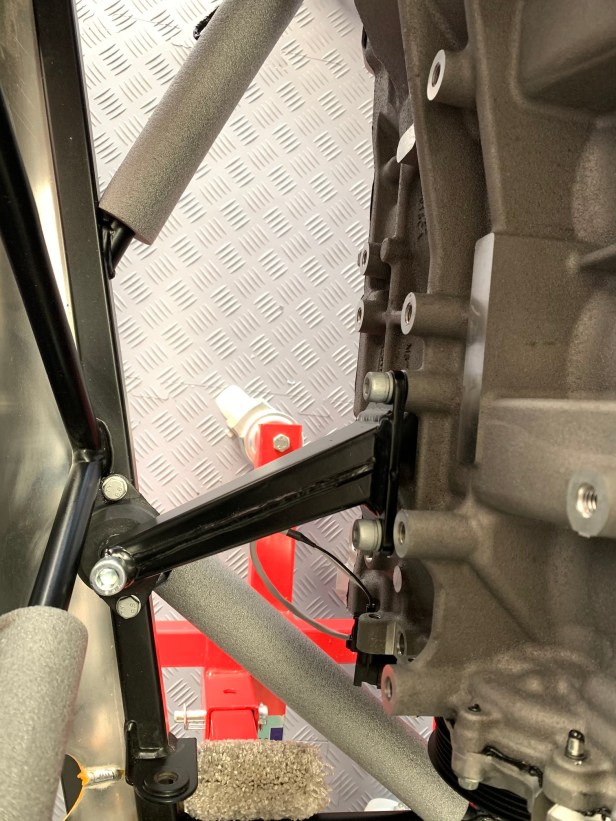
Loosen the engine mount to get the bolt into the rubber 
You may need to loosen the lhs mount to get the bolt started 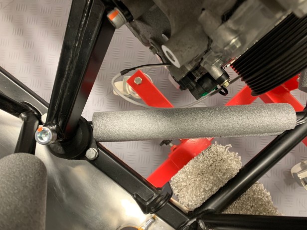
All torqued up
Only when you have all the bolts torqued up is it time to remove the hoist.
The manual (2015c) calls for thread lock on the M14 mounting bolts. I wonder if this is old information, because a shake-proof washer is provided, but I still applied some Loctite 243 (https://www.henkel-adhesives.com/us/en/product/threadlockers/loctite_243.html) just in case.
I also applied the usual smear of copper grease to the rest of the bolts, and I marked them after the torque was applied to remind me that these bolts are torqued up to specification.

Thread lock applied 
Gearbox mount torqued up
- Gearbox Mount to Chassis: 20Nm
- Gearbox to Gearbox Mount: 40Nm
- Engine Mount Rubber to Chassis: 20Nm
- Engine Mount to Engine Mount Rubber: 41Nm
- Engine Mount to Engine: 34Nm
About to remove the hoist 
All done 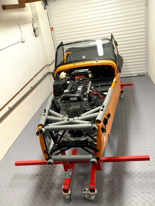
Hoist packed away
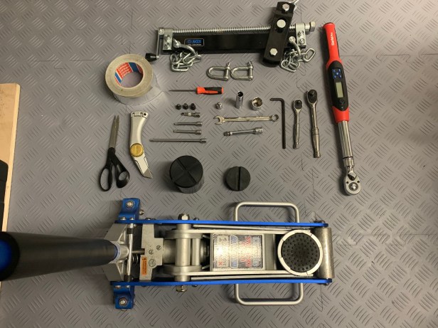
Tools Used
- Engine load leveller
- Chains
- Four Shackles
- 22mm 3/8 Socket
- 13mm 3/8 Socket
- 6mm hex 1/4 Socket
- 8mm hex 1/4 Socket
- 3/8″ hex 1/4 Socket
- Selection of 1/4 extensions
- 1/4 3/8 adaptor
- 6mm Allen key
- 1/4 Ratchet
- 3/8 Ratchet
- 3/8 extension
- Scissors
- Knife
- Aluminium Tape
- 3/8 Torque wrench
- Trolly jack
- Small lifting block
- Large lifting block
- 13mm combination spanner
- Engine hoist
- Straight pick

I pretty much followed Chris’s advice for our 360R engine install in a S3 chassis. We used a 250kg ratchet strap on the LHS mount and that worked well. As many others have found, the control of Pitch, Yaw and Roll makes it a 3D puzzle and interestingly it was a slight roll of the engine which was preventing us starting the long engine mount bolts even when they looked to be exactly lined up.
I found it useful to have two jacks in the gearbox area so if one started to go out of alignment it could be replaced by another rather than having to reverse out of the difficulty.
The most time consuming and fiddly part was holding the gearbox mount caphead bolts against the nyloc nuts. Getting a 6mm hex into the top of the caphead bolt was very awkward and I would think it would be much easier if the bolt had a normal flat head.
The torque we used from Caterham (March 2021) were as follows
Rubber Engine Mount to chassis 20Nm
Engine Mount to Engine 47Nm
Gearbox mount to Chassis 20Nm
Gearbox to Gearbox mount 60Nm
Engine mount to Rubber Mount 81Nm.
LikeLike
… and for those of you like me doing an SV build who were hoping that things wouldn’t be as tight as the S3… not a chance…
Chris’s process works very well and it’s well worth following it to the letter. To Nick West’s comment about tricky access to the gearbox mount caphead bolts, we worked out that you can jack the gearbox right up into the top of the tunnel by quite a few centimetres above its mounting position, which gives you a lot more room to get (in our case) an allen key into the caphead bolt heads to hold them in position reasonably easily. It’s still a bit tight, but it’s almost impossible with the gearbox lowered. I checked the alignment of the 2 large gearbox bolts through the mount into the gearbox before raising the gearbox and tightening the 4 mount bolts. I then took the plunge and torqued them, before lowering the gearbox fully down onto the mount and screwing in the two large mounting bolts. The gearbox needed a bit of wiggling to get the bolts in but it wasn’t too difficult.
LikeLike
Hi,
Can you say why you used 1/4 inch drive hex bits (6 and 8mm and 3/8″), eg. did you find 3/8 drive too cumbersome? Could be useful to know before I start my 420 engine installation. Thanks,
Mark
LikeLiked by 1 person
Hi Mark, The 3/8” hex bit is for the engine mount bolts that go through the mounts into the rubber blocks. The other two sizes are just mounts to engine and chassis mounting plate fixings. The socket drive size was not important; it is just the size dictated by hex bits I have. Hope this helps, and good luck with the install. Chris.
LikeLike
Oh and forget to say I am sure 3/8 drive wouldn’t be to cumbersome.
LikeLike
Thanks for that, Chris. I have all the necessary hex bits in 3/8″ drive, so was interested to know why you used 1/4″ drive…. and you’ve answered my question, so thank you! My engine is ready to install and I’m reading up as much as possible on what seems to be a slow, fiddly operation. As with many things, the first time undoubtedly has a big learning curve, even taking heed of as many tips & hints as I can.
BTW, I have enjoyed reading your build blog, very interesting.
LikeLiked by 1 person
Mark, if you need help send me a direct message, always happy to help. Chris.
LikeLike
Hi Chris,
I followed your example and used a ratchet tie, run through the eye of the n/s engine mounting bracket, to raise the n/s of the engine before starting to lower it into the chassis. This made getting the engine aligned and in place actually quite straightforward, more so than I had anticipated after reading some other blogs. So thanks for that!
Re. David’s comments on the caphead bolts which secure the gearbox bracket to the chassis rails. For anyone else reading this before doing the install, I can say that getting to these was no problem using a hex bit on a short 1/4″ wobble bar fitted in turn to a long 1/4″ wobble bar. Using a ballend hex bit also makes it easier to locate the bit into the cap head. And have one person above, lowering the wobble bar, whilst the other is below the car guiding the bit into the cap head.
LikeLiked by 1 person
[420R S3, Q1 2022]. This was my first engine installation and as per the other comments I found following Chris’s procedure to be incredibly helpful. A couple of additional observations…
Lining the tunnel with cardboard from cornflake packages (other breakfast cereals are available) helps prevent any damage during installation – it’s thin enough (just!) not to get in the way and be removable afterwards.
I was fortunate enough to have two people to help me – one experienced friend whose hoist and leveller I was using, and a very understanding wife who was trusting enough to lie under the car and help finesse/shove the gearbox into place. With the hoist taking the weight, the two of us were able to steer and twist the engine down and in relatively easily, whilst having someone looking along the tunnel helped keep the gearbox straight and limit the number of times we got stuck and had to reverse slightly. I think the biggest upside of this approach is you can do away with both the ratchet strap on the engine and the jack underneath, making the whole process more fluid – so I do recommend it if you can find enough people willing to spare a few hours.
Once the engine was correctly in place front-to-back, with the gearbox bracket bolts loosely done up, I connected one engine mount and was surprised to find a 6mm lateral gap between the other engine mount and the chassis mount. No amount of loosening everything off and then tightening was going to close that. I therefore stopped at this point, leaving the hoist attached, and contacted Caterham who told me this wasn’t unusual (!) and put a set of washers in the post to me. The washers were 2mm thick and placed between the engine and the mounts – 2 on one side and 1 on the other to be as balanced as possible. It was a real faff to fit these with the engine sat in the car, but using the hoist to take the weight meant I could do it alone. Once these were in place, everything lined up and could be torqued appropriately.
LikeLiked by 1 person