
I would recommend getting some help when installing the differential, but the method I use was created when I didn’t have the help needed. Thankfully this time my wife (who is a dab hand with an engine hoist) saved me from countless times crawling out from under the car.

Out of the box 
Engine Enamel 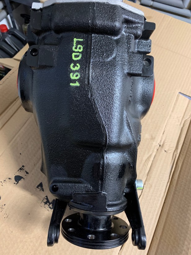
Ready to install
The diff as supplied from Caterham (being a LSD) isn’t supplied with oil. It’s a BMW unit which has been machined to fit a carrier that matches the original Ford Sierra differential bolt pattern. The machining leaves some bare metal areas which will rust over time, so I decided to break out the Engine Enamel and paint the bare metal areas. My advice is to loosen the oil fill plug at his stage, to make filling it with oil once installed easier. For some strange reason the size of the oil fill plug is different to my previous 360R, so I didn’t have the correct size tool and I had to order a 14mm hex socket.
Engine hoist used to lift 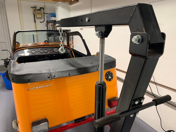
Hoist location 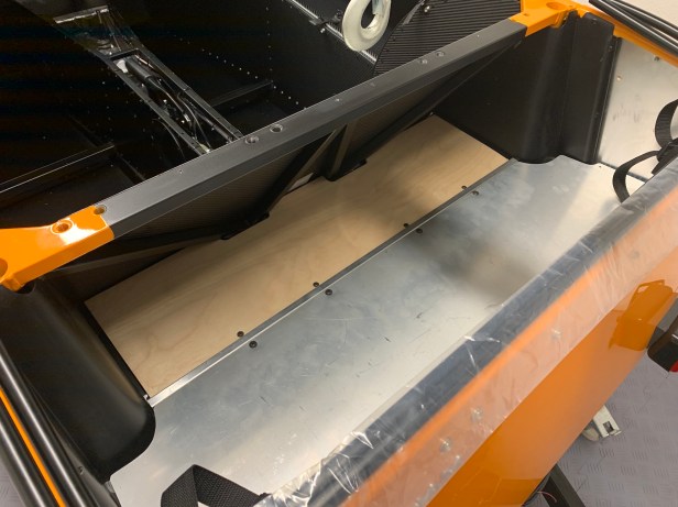
Boot cover removed 
Boot board removed
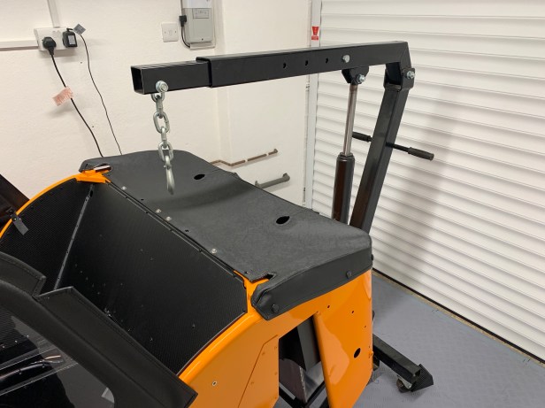
Next I broke out the engine hoist, which I use to lift the differential instead of attempting to lift it from underneath without a proper transmission jack. It’s one of the advantages of building on wheeled axle stands: I am able to move the engine hoist around even in a small single garage by moving the chassis to one side of the garage. I then removed the boot cover and wooden boot floor.
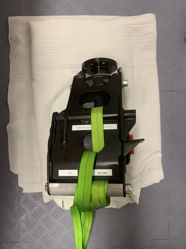
Ratchet straps attached 
Straps attached to the hoist 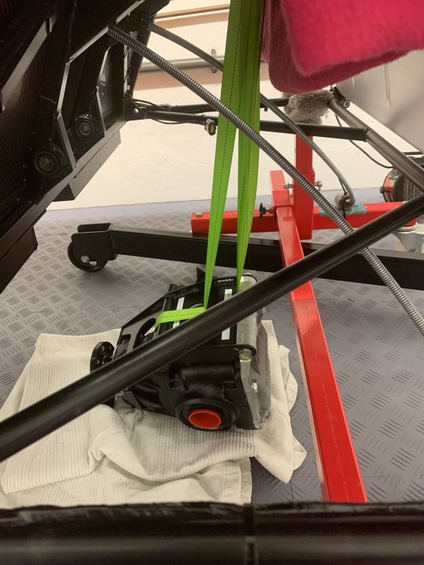
Ready to lift
Two ratchet straps (rated at 250Kg each so should be strong enough) were attached to the differential. The important bit is that they exit the differential at the rear (near the aluminium back plate) so they can pass through the opening. I used pipe lagging as usual to protect the chassis.
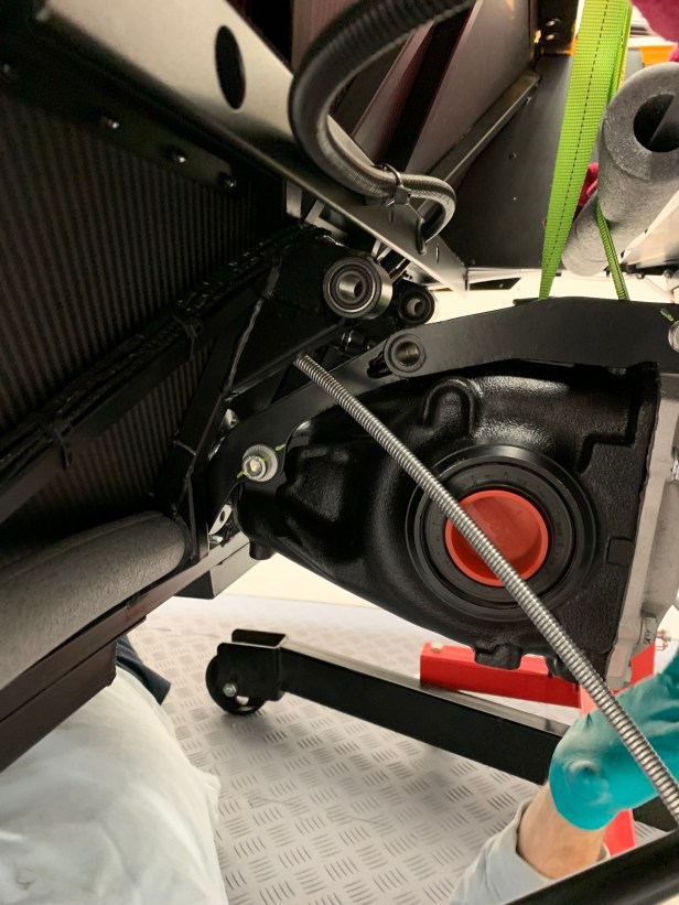
I look to locate the bottom bolts first, not with actual bolts, but with pin punches (the largest possible). It’s difficult to see the pin punch in the photo, because the handle is covered with pipe lagging.
Top hole held with pin punch 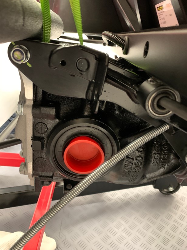
Time to get the handbrake adjuster in the correct location
The lifting then continues to locate the top holes, again with more pin punches.

Handbrake adjuster bracket 
Handbrake removed 
Before location 
After location
With the differential now in place, all be it with pin punches, I decided to locate the handbrake adjuster in the differential bracket. Like the other handbrake cable brackets, it’s only possible to do this by passing the black inner cable through the bracket, which meant removing the handbrake lever installed earlier. I wish I had known this before installing the handbrake.
Once I had the handbrake adjuster in place, it was time to fit the lower differential bolts. To get the holes aligned I worked my way up through my selection of pin punches until the punch was almost the same size as the bolt.
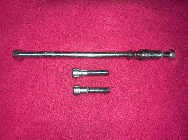
Fixings 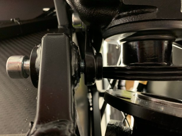
Bottom bolt gap to fill with washers
Caterham supply a large number of spacer washer in three widths. With one of the bottom bolts pulled up tight, I could measure the gap I needed to span with the washers. Following the new manual (v1.2 and v2.0), the spacing washers should be placed evenly between the two bottom bolts. Don’t forget the Schnorr washer under each bolt head and nut, unlike the new manual’s (v1.2 and v2.0) diagram. With the gap I had I could fit four medium washers and one thin shim, so I went two each side, plus that thin shim on the left hand side. At this stage I didn’t tighten the bottom bolts.
UPDATE – See Sean’s tip in the comments if you have problems keeping the spacing washers in place during the install.
Lots of copper slip on the top bolt 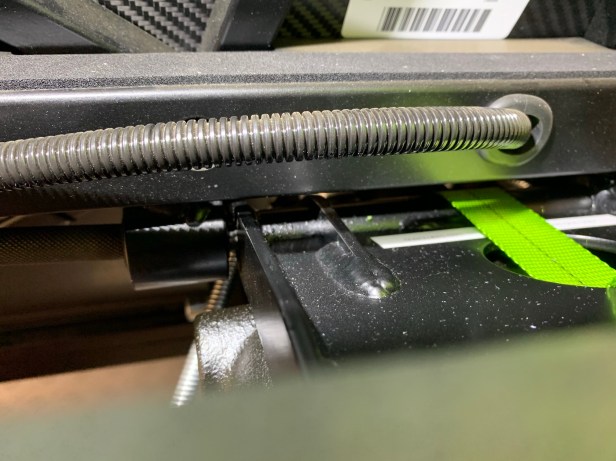
Gap to be filled with washers 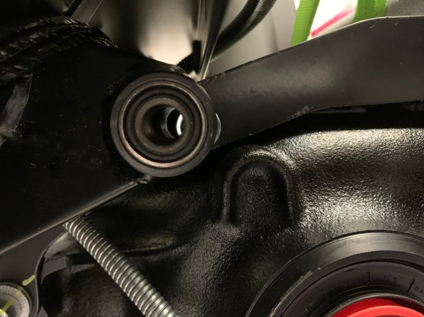
Align the washers with the pin punches 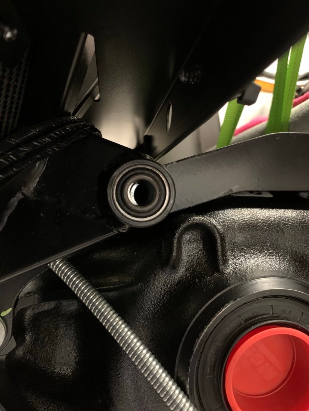
Washers nearly aligned
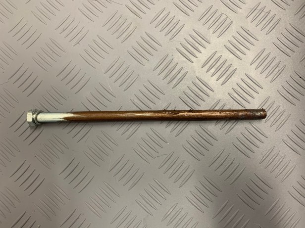
For the top bolt I needed two thick spacers on one side and one thick spacer and a thin shim on the other. I put a lot of copper slip grease on the top bolt, because the this bolt is not easy to install. To get the bolt started, I aligned the washers, pin punches again are your friend here. Initially the bolt can be pushed in by hand, but soon the dead blow hammer came into play.

Top bolt about to push through 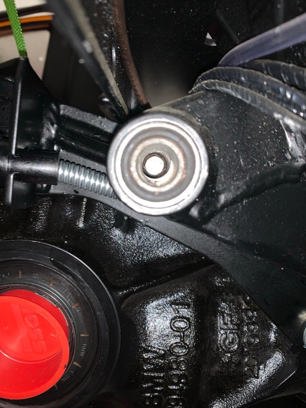
Align the last washers
As it comes to the other side, again the washers are the initial problem and pin punches can get you close to getting everything aligned but, to make that final push, a bit of tool abuse was needed. I used a 1/2” drive long extension as a drift and the dead blow hammer to push it through that final bit.
Bolts torqued Prop shaft bolts fitted 
Labels serve as a reminder 
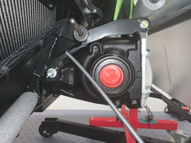
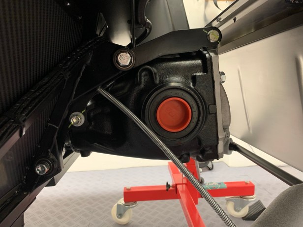
Differential installed
I torqued the differential bolts to 81Nm at the bottom and 61Nm at the top. At this stage I didn’t attempt to torque the prop shaft to diff bolts to 47Nm, because I didn’t have a way to lock the drivetrain. I will do this when the handbrake is working. I found fitting the bolts from above easier, mainly because the panel above hasn’t been installed yet.

Tools Used
- 250Kg ratchet straps x 2
- Engine hoist
- Pin punches (various)
- 1/2” drive long extension
- Dead blow hammer
- 10mm 1/4” drive hex socket
- 8mm 1/4” drive hex socket
- small 1/4” drive extension
- 1/4” drive to 3/8” drive adapter
- 1/4” drive ratchet
- 3/8” drive ratchet
- 3/8” torque wrench
- 3/4” deep 3/8” drive socket
- 3/4” combination spanner
- Philips screwdriver

Hi Chris, Sean here from Savannah (USA) thank you for the tips, you seem to be building your Caterham almost insync with my build here in Savannah. Your site has been most helpful. One additional tip on the shims I decided to coat the shims with some copaslip as to hold them together, so they don’t keep falling out, once I had decided the thickness I needed.
LikeLike
Hi Sean, Thanks for the comments, and thanks for the tip. I will add an update to the post.
LikeLike
I cannot recall now if it was these shims or the A-frame ones, but I resorted to super glueing some of the washer stacks!
LikeLike
Hey Simon, no worries, I actually had my fiance’ use the hoist with 2 straps on it, an i was under the car – it worked out beautiful!!
I do have a couple of other questions.
1) I have 2 brown wires coming from both the starter motor and the alternator, these come out at the back of the engine close to where the battery would be, are these the earth wires or positive. The dealer here didnt know what they were?
2) I have 2 extra wires with “female” connectors coming out of the top of the gear box close to where the reverse harness attachment goes( I connected this harness to the plug that was in the tunnel) so where is the “male” wire for this connection?
I have looked thru the manual for both of these and can not find anything.
Any suggestions please.
Thank you,.
Sean
LikeLike
Hi Sean,
I assume you have the current 5 speed gearbox. The switch on the side is the reverse switch, and the switch on the top is the “not used” neutral switch. Have a look at my “Handbrake and Gear lever” post for what I did. The only brown wires I know about are the large alternator to starter motor connection, but your car is a US build, which I believe have the engine sourced from a different supplier, so maybe there are differences. Send me a message from the “Contact” page, and I will reply, maybe you could then send me a picture.
Chris.
LikeLike
Hi Chris,
yes I have the 5 speed 360S model. I will take another look at your post. Great info on the neutral switch, I think I then connected the wrong wire, I will check in the morning. Ok will send you a note and Pic. Thank you
Sean
LikeLike
Hi Chris,
Your hoist technique is a godsend as it leaves the area clear to work underneath the diff, which is almost impossible if you use a jack. I also used the copper slip technique for trying to keep the washers in place (thanks Sean).
I had real trouble installing my diff – the alignment between the diff brackets and the chassis mounts wasn’t good. I tried your technique of installing the bottom bolts first – and not fully – which was easy enough, but then the long top bolt wouldn’t even start through the first mount. After numerous permutations and using the hoist to try and get better alignment, the only way that worked for me was as follows :
– install the long top bolt through the first mount and the diff, but not through the mount on the other side
install the two bottom bolts but leave not fully tightened
– then hammer the top bolt through the mount on the other side
– in my case, hammering the top bolt through started to push the rubber bush on the other side out of the chassis mount. To prevent this I managed to get a clamp around the diff and the rubber mount on the other side which stopped it from being hammered out. Then I could hammer the bolt in, finally, and attach the nut and schnorr washer.
The moral of the tale is keep persevering – there is sufficient play on the rubber mounting bushes on the chassis to eventually cope with poor alignment between the diff bracket and the chassis mounts, but working out the right sequence to get the bolts installed can be a long painful process. Hoisting hard can also help improve things by that critical millimetre at times.
Dave.
LikeLiked by 1 person
Hi Dave,
How is the build going.
Would love to know.
Sean
LikeLike
Hi Sean – it’s all done thanks, and gone off for its post-build check back at the dealer who I bought it from. My email is david@berclas.co.uk, if you’d like more details you can email me directly.
LikeLike
I was not looking forward to the differential installation. Even with the benefit of a transmission jack that would allow fine grain positioning of the diff in pitch and roll, I expected a battle. Initially all went well, and the bottom bolts were fitted loosely with equal washers. However, no amount of adjustment of the jack would allow the top bolt to start. The main problem was that the diff carrier was hard up against the cross rail which prevented the final few mm of movement needed to clear a passage for the bolt. Eventually I did what others before me have done and filed a nose on the bolt. Though extremely tight this did just give enough leeway to feed the bolt through the washers.
Although the diff was now fitted, I was concerned about vibration as it was touching a chassis member without any intervening rubber bushing. I raised this with Caterham and got the following reply:
“I have had similar feedback from customers but I am not aware of any changes to either the differential carrier, nor the right angle chassis bracket which would explain why we are seeing this contact.
If the fouling is occurring between the diff cage and the boot floor then I have been advising customers to add additional spacing between the boot floor divider and the boot turrets. This has been common practise since the introduction of the BMW diffs, but occasionally this does require further adjustment once the diff is in place. I would also advise placing a piece of protective foam between the two potential contact points in order to further prevent the chance of vibrations being transmitted.
If the fouling is occurring between the diff cage and the right angle chassis bracket then I have been advising customers to gently bend the bracket away from the cage and insert a piece of rubber trim between the two contact points. This is the quickest and easiest solution as this is not a structural part.”
On receipt of this advice and with no little difficulty I was able to prise the cross member away from the diff carrier sufficient to insert a piece of IVA trim. Inevitably there was some minor paint damage and I treated this with black Hammerite before fitting the trim.
I reported back to Lee who subsequently wrote:
“It is something which we are currently working with our chassis manufacturing facility to resolve moving forwards. The CAD tolerance between the cage diff cage and the cross rail is only 1.5mm at best, therefore it’s very easy for this gap to be eradicated during the chassis assembly.”
If I had known or been forewarned of the problem, it would have been much easier to gently bend the cross rail before the diff was fitted. It is much more difficult to do so with the diff in place.
LikeLiked by 1 person